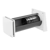
Inventer IV-14 Zero
Ventilation System Design
We would love to design the perfect ventilation system for your needs. Our design will provide the best performance and comfort levels and comply with all necessary building regulations.
Inventer heat recovery fans work in pairs and require a controller. A controller can power more than one fan.
If you decide not to consult with our technical team, this will be at your own risk. A professional system design is always recommended.
Product Overview
Main purpose
Ultra-quiet and energy efficient extraction of stale air, replacing it with filtered fresh air from outside. Recovers up to 87% of heat from the extracted air to warm-up colder air coming in from outside. Functions as a heat recovery ventilation unit within a decentralised ventilation system.
Use it on
External walls up to 495mm thick (with standard wall-sleeve) or up to 745mm thick (with large wall-sleeve), typically in bedrooms and living areas where quietest possible noise levels are required. Suitable for block, concrete, stone, timber frame and brick constructions. Minimum compatible wall thickness is 255mm. Requires a 225mm hole in the wall.
Overview
The IV-14 Zero is an ultra-quiet, low-energy, sound absorbing, heat recovery ventilation unit with a heat recovery rate of 87%. It includes a reversible fan that can silently switch air flow direction to extract air then supply air as it’s needed. There is also a thermal accumulator for heat recovery, an integrated dust filter, a weatherproof stainless-steel exterior hood, and sound insulation built-in to reduce noise from outside. This combination of features and components ensure optimum heat recovery with maximum air flow and minimal sound emission and transmission of noises from outside.
Features
- 87% heat recovery
- Extremely quiet fan. 10-31 dB (A)
- Sound insulation reduces external noise by up to 56 dB
- 3W energy consumption
- 5-year guarantee
- Built-in temperature sensor
- Unaffected by strong wind outside
- Stylish stainless steel exterior hood
- Closable inner cover
- Energy efficient
Benefits
- Inventin sound insulation in the wall-sleeve guarantees optimum heat recovery with maximum air flow and minimal noise
- Recovers 87% of heat from extracted air to warm up the inbound air so a constant indoor air temperature and comfort level is maintained
- Exceptionally quiet fan 10-31 dB (A) is ideal for bedrooms or living areas where minimum noise is required
- Energy efficient 3W fan lowers running costs and carbon emissions of the building to help make an active contribution to the environment
- Built-in G4 dust filter can be cleaned and reused many times
- Additional filters are available to provide total control of all allergens entering the building and ensure the highest levels of indoor air quality can be achieved
- The inner cover of the fan can be closed to seal the hole in the wall. Great for preventing unwanted draughts when the fan is switched off or for when extreme noise or odours occur outside.
- When it is below 5° C outside, the fan adapts its heat recovery cycle to recover more heat and ensure cold air is not supplied to the building.
Questions
There are currently no questions and answers published for this product
Technical Details
Key Technical Data
Installation Guide

How to Install
Turn the power off during electrical works. All electrical connections must be carried out by a qualified professional. Seek professional advice for planning and installation of all electrical works.
The IV-14 Zero receives its power from an Inventer sMove controller. This should be installed first by following the controller’s installation guide. The wire from the controller must be long enough to reach the connector on the fan’s power cable. Depending on the wall thickness, this connector could be inside the hole, so please ensure the wire is long enough to reach right to the back of the hole.
When installed on an external wall, a 225mm wide hole will be required. The hole should have a 2° fall to the outside to allow any condensation to run off to the exterior. In walls made from brick, concrete or stone, this should be cut with a 225mm masonry core drill.
For newbuilds, a wall mounting block is available. This block can be incorporated into the brickwork of the building for easier installation without the need for core drilling. It incorporates insulation and a 2° slope.
The best position for the fan on the wall should be worked out in advance before drilling. The fan must be positioned so the centre of the fan, internally or externally, will be at least 250mm from the edge of a window or ceiling and at least 450mm from the eaves of the roof. The internal end of the fan should be situated away from radiators, thermostats, sensors and heat sources and should not be obstructed by furniture, fixtures or fittings. Locating the unit near sensitive artworks/paintings should be avoided to avoid any damage caused by the drying effect of near constant air movement.
Once a suitable hole with a 2° fall to the outside has been created, the wall-sleeve can be cut to length. The wall-sleeve has a notch at one end. This notched end should be on the interior side of the hole. You must cut the other end. The required length of the wall-sleeve is equal to the thickness of the wall plus an extra 10mm.
Hint: You may find it easier to judge the length required by fitting the wall-sleeve into the hole and aligning the interior end flush with the wall (consider any internal plaster/finishes to be added later and adjust as necessary). Then make sure the wall-sleeve has a 2° slope towards the exterior. You may need to use the supplied wedges to align and secure the wall-sleeve at the correct 2° incline. From the exterior, draw round the protruding pipe with a pen or pencil to mark the wall level on the sleeve. You could use a spacer or your finger between the pen and the wall to draw the line 10mm away from the wall surface, or you can just mark the wall line, remove the sleeve from the wall and draw a second line on the sleeve 10mm further along. Once you have a suitable line to mark the thickness of the wall plus 10mm, cut the sleeve and reinsert it into the wall replacing the wedges as needed.
After it is cut to length and inserted into the hole, the wall-sleeve should be rotated so the notch is towards the bottom and near where the power wires will be. The IV-Light is supplied with a white cylindrical insert. This can be inserted into the wall-sleeve to temporarily block the hole and prevent draughts while you continue the installation.
The Wall-sleeve should be a snug fit in the hole and sealed airtight at both ends. To help centre the wall-sleeve in the hole, the supplied wedges can be used (at either end) to adjust the position of the wall-sleeve and make sure the wall-sleeve has at least 2° of slope to the outside. The wedges can remain in place. Where any wedges protrude from the wall, this can be cut with a sharp knife so it is flush. Seal gaps of up to 6mm between the wall-sleeve and wall with Pro Clima Orcon F airtight sealant. For bigger gaps of up to 20mm, use Aerosana Visconn Fibre. If any gaps exceed 20mm, fill with mortar, leave it to set then seal all around with Orcon F or Aerosana Visconn Fibre. Alternatively, an expanding foam filler can be used to fill gaps around the wall-sleeve. Once set, the foam and the wedges can be trimmed flush to the wall. As this material can crack over time and may not provide a permanent airtight seal, the foam must also be covered over and sealed with Aerosana Visconn Fibre to remain airtight for the lifetime of the building.
If the wall has no plaster or render on it and will be plastered or rendered later, a pair of 180-220mm Pro Clima Roflex Solido airtight grommets can be used to seal either end of the wall-sleeve to the wall. This grommet is stuck to the surrounding masonry then plastered over to finish.
The external weather protection hood is installed next. The external baseplate should be orientated so the horizontal grill section is at the bottom. A spirit level should be used to make sure everything is horizontal then holes can be marked and drilled (to a depth of 5mm) with an 8mm drill bit then the supplied wall plugs can be inserted.
The foam weatherproofing tape should be applied around the outside edge on the back of the baseplate then the baseplate can be screwed to the wall. Use the supplied screws and washers. The outer grill will then slide down over the baseplate to complete the external part of the installation.
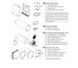
Work now continues from the interior side. The temporary insert used to plug the wall-sleeve must now be removed. The Inventin sound insulation should then be rolled into a cylinder and inserted all the way into the wall-sleeve to fully line the interior. Cut off any extra Inventin insulation with a sharp knife.
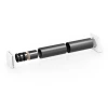
The ceramic honeycomb thermal accumulator is inserted next. Hold the handle on the accumulator and push all the way to the back of the wall-sleeve. Then insert the fan with the wire facing toward the interior of the room. Rotate the fan, if necessary, to align the wire location with the notch in the wall-sleeve. Depending on the thickness of the wall, you might need to connect the fan to the power supply (the wire from the controller) before inserting the fan all the way in the wall-sleeve.
The inner cover can now be installed. The cover has two parts: a baseplate and a smooth top cover. The smooth top cover needs to be separated from the baseplate by pressing the small release buttons at each corner. The power wire (from the controller) should now be connected. Use the four bolts and allen key to screw the baseplate to the four holes on the wall-sleeve. Do not over-tighten the bolts. The filter is then inserted into the baseplate. The smooth top cover is then pressed over the filter onto the baseplate and clipped into place.


